EMBUX

embedded linux


  • Home

  • Products

  • Events

  • Tags

  • Search

uboot-lvds-panel-configuration

Posted on 2016-04-29

uboot lvds panel configuration

Environment

U-BOOT version: 2014

Source Reference:

Git: http://git.freescale.com/git/cgit.cgi/imx/uboot-imx.git/
Branch: imx_v2014.04_3.10.53_1.1.0_ga File: ~/board/freescale/mx6sabresd/mx6sabresd.c

reference example

1
2
3
4
5
6
7
8
9
10
11
12
13
14
15
16
17
18
19
20
21
static struct display_info_t const displays[] {
{
.bus = -1, .addr = 0, .pixfmt = IPU_PIX_FMT_RGB666, // IPU_PIX_FMT_RGB24
.detect = NULL,
.enable = NULL,
.mode = {
.name = "Hannstar-XGA",
.refresh = 60,
.xres = 1024,
.yres = 768,
.pixclock = 15385,
.left_margin = 220,
.right_margin = 40,
.upper_margin = 21,
.lower_margin = 7,
.hsync_len = 60,
.vsync_len = 10,
.sync = FB_SYNC_EXT,
.vmode = FB_VMODE_MONINTERLAED,
}
},
  • pixfmt: 18bit or 24bit

    • IPU_PIX_FMT_RGB666

      1
      2
      3
      4
      5
      6
      7
      8
      9
      10
      11
      12
      static void setup_display(void)
      {
      ...
      reg = IOMUXC_GPR2_BGREF_PRMODE_EXTERNAL_RES
      ...
      | IOMUXC_GPR2_DATA_WIDTH_CH1_18BIT
      ...
      | IOMUXC_GPR2_DATA_WIDTH_CH0_18BIT
      }
      ```
      - `IPU_PIX_FMT_RGB24`

      static void setup_display(void)

      {
          ...
          reg = IOMUXC_GPR2_BGREF_PRMODE_EXTERNAL_RES
          ...
              | IOMUXC_GPR2_DATA_WIDTH_CH1_24BIT
          ...
              | IOMUXC_GPR2_DATA_WIDTH_CH0_24BIT
      }
      
      1
      2
      3
      4
      5
      6
      7
      8
      9
      10
      11
      12
      13
      14
      15
      16
      17
      18
      19
      20
      21
      22
      23
      24
      25
      26
      27
      28
      29
      30
      31
      - name: panel name checked in boot-env setting `panel`
      - refresh: refresh rate, set to typical
      - xres: x resolution / active width / H-display area
      - yres: y resolution / active height / V-display area
      - pixclock: pixel clock
      - calculate formula: `pixclock=(10^12)/clk_freq` (clk_freq: DCLK freq)
      - pixclock = `10^12 / (1024+220+40+60) * (768+21+7+10) * 60` = `15385 ps` (ps: pico-sencond, 10^(-12) second
      - Horizontal
      - left_margin: left margin / HS back porch (HBP)
      - right_margin: right margin / HS front porch (HFP)
      - hsync_len: horizontal sync length / HS pulse width (HPW)
      - Horizontal blanking time: HBP + HFP
      - Vertical
      - upper_margin: upper margin / VS back porch (VBP)
      - lower_margin: lower margin / VS front porch (VFP)
      - vsync_len: vertical sync length / VS pulse width (VPW)
      - Vertical blanking time: VBP + VFP
      - sync: FB_SYNC_EXT, external sync
      ~/drivers/video/videomodes.h
      - vmode: this is a progressive video mode, so set vmode to FB_VMODE_NONINTERLACED.
      ~/drivers/video/videomodes.h
      ## HDMI Full HD 1920x1080

{ .bus = -1, .addr = 0, .pixfmt = IPU_PIX_FMT_RGB24, .detect = NULL, .enable = do_enable_hdmi, .mode = { .name = “HDMI”, .refresh = 60, .xres = 640, .yres = 480, .pixclock = 39721, .left_margin = 48, .right_margin = 16, .upper_margin = 33, .lower_margin = 10, .hsync_len = 96, .vsync_len = 2, .sync = 0, .vmode = FB_VMODE_NONINTERLACED } } ```

ICM-3011 Announcement - EMBUX 3.5’’ Board

Posted on 2016-04-22 | In events

EMBUX, the ARM based embedded platform and integration services provider, announces the new ARM-based industrial-grade 3.5” NXP i.MX6 CPU Board, ICM-3011, is a low profile NXP i.MX6 design with a rich variety of I/O functions to fulfill an assortment of space-limited applications. ICM-3011 can apply to many embedded applications such as slim signage boxes, slim panel PCs, vending machines, nursing carts, small POS systems, and automotive infotainment.

Rich I/O Interface for Best Performance

ICM-3011 incorporates ARM® Cortex™-A9 architecture for next-generation industrial and automotive applications, which combines scalable platforms with broad levels of integration and power-efficient processing capabilities particularly suited to multimedia applications. With a power-efficient processing capabilities of leading edge 3D and 2D graphics, as well as high-definition video and a new level of multimedia performance to enable an unbounded next generation user experience. ICM-3011 offers a variety of I/O interfaces including : 2 x 18/24-bit LVDS output, 1 x HDMI, 1 x Gigabit LAN, 4 x USB 2.0, 1 x USB OTG (micro USB type), 4 x RS-232 (8-wire), 2 x RS-232 (4-wire), 2 x RS-485, 2 x CAN-bus interface, 1 x SDIO, 1 x standard SD, 1 x SIM card socket and 2 x half/full mini PCIe.

Thin Design for Flexible Embedded Integration

ICM-3011’s thin design provides a high degree of flexibility and allows the system to be easily integrated into low-profile enclosures for a wide range of applications. The total height of ICM-3011 is only 25mm, which can easily meet compact size-requirements for slim chassis applications. ICM-3011 not only offers enhanced stability but also durability.

Innovative Reliability Design

ICM-3011 is an ARM-based industrial and jump-less design, which develops with all solid capacitors and 1% precision resistors, and all boards are also guaranteed with over 100 times on/off cycling test before factory output to ensure the best quality that EMBUX commits to customer satisfaction.

Tailor-made Operating System

EMBUX offers the precise adaptation to customer requirements. Not only low interdependency among modules allows for easy modification, but also reliable peripheral drivers support various resolution and dimension for LVDS panels, Touch (RTP/CTP), GPIO, CANBus, SDIO, watchdog timer, HDMI, RS-232 and RS-485. Supported operating system including Yocto (1.6.2), Android (5.0.2) and WEC7 - hardware drivers for these are built-in and readily available.

ICM-3011 Main Features

▪ All-In-One Fanless SBC  
▪ All solid capacitors & 1% precision resistors design  
▪ Industrial & jumper-less design  
▪ Power on/off test over 100 times before shipment  
▪ Support dual LVDS panels  
▪ Support dual channel LVDS panel up to 1920X1080 resolution  
▪ 3G/Wi-Fi solution available  
▪ NXP i.MX6 DualLite 1.0 GHz Cortex-A9  
▪ Onboard DDR3 2GB  
▪ 4GB eMMC NAND Flash and 8MB NOR Flash  
▪ 2 x 18/24-bit LVDS  
▪ 1 x HDMI 1920x1080  
▪ 1 x 10/100/1000 Mbps Ethernet  
▪ 4 x USB 2.0  
▪ 4 x RS-232 (8-wire), 2 x RS-232 (4-wire)  
▪ Line-In (Header), Line-Out (Phone Jack), Mic-In (Phone Jack)  
▪ 2 x CAN  
▪ 1 x Standard SD slot, 1 x SDIO slot  
▪ 1 x half/full-size mini-PCIe (PCIe & USB signal)  
▪ 1 x half/full-size mini-PCIe (USB signal)  
▪ 1 x SIM card socket  
▪ Wide range power input from 10.8V to 26.4V  

ICM-3011 will be available by Q2 2016, for more information, please visit the website www.embux.com or contact EMBUX directly.

Yocto 1.6.2 running on ICM-3011

Posted on 2016-04-07 | In events

EMBUX is glad to introduce the yocto 1.6.2 test build running on the ICM-3011.

ICM-3011 is a 3.5’’ ARM-based embedded board, powered by NXP (Freescale) i.MX6, provides multi-integrated functions for easy implementation.

Please refer EMBUX website for latest update.

Information

  • uboot: 2014.04
  • kernel: 3.10.53
  • rootfs: Yocto 1.6.2 (Daisy)

Below is the introduction for Yocto 1.6.2 (Daisy) from NXP document:

  • What is the Yocto Project?

    “A Linux Foundation workgroup whose goal is to produce tools and processes that enable the creation of Linux distributions for embedded software independent of architecture”

  • NXP (Freescale) Yocto Project

    • Linux distributed build system
    • Replacement for LTIB
    • Higher integration with community
    • Flexible release targets

ICM-3011 Main Features

▪ All-In-One Fanless SBC  
▪ All solid capacitors & 1% precision resistors design  
▪ Industrial & jumper-less design  
▪ Power on/off test over 100 times before shipment  
▪ Support dual LVDS panels  
▪ Support dual channel LVDS panel up to 1920X1080 resolution  
▪ 3G/Wi-Fi solution available  
▪ NXP i.MX6 DualLite 1.0 GHz Cortex-A9  
▪ Onboard DDR3 2GB  
▪ 4GB eMMC NAND Flash and 8MB NOR Flash  
▪ 2 x 18/24-bit LVDS  
▪ 1 x HDMI 1920x1080  
▪ 1 x 10/100/1000 Mbps Ethernet  
▪ 4 x USB 2.0  
▪ 4 x RS-232 (8-wire), 2 x RS-232 (4-wire)  
▪ Line-In (Header), Line-Out (Phone Jack), Mic-In (Phone Jack)  
▪ 2 x CAN  
▪ 1 x Standard SD slot, 1 x SDIO slot  
▪ 1 x half/full-size mini-PCIe (PCIe & USB signal)  
▪ 1 x half/full-size mini-PCIe (USB signal)  
▪ 1 x SIM card socket  
▪ Wide range power input from 10.8V to 26.4V  

Reference

  • EMBUX Products
  • NXP(Freescale) Public Git
  • Yocto websit

How to setup different display configuration of ICM-3011 with WEC7 OS

Posted on 2016-04-06

[Equipment]

  1. Laptop/Desktop, with Tera Term VT (user can download from internet directly)
  2. EMBUX ICM-3011 series
  3. Power adapter for ICM-3011 series
  4. USB to serial port cable
  5. HDMI/LVDS panel, please check with EMBUX LCD compatible list

[Environment]

  1. Make sure the DIP switches setting as below:
  2. Connect COM port(JCOM1) with Laptop/Desktop
  3. Run Tera Term and

[Procedure]

  1. Power on ICM-3011 series and press space on Tera Term(within 3 seconds) to enter Freescale i.MX6 SOC Main Menu
  2. Select “8” to Enter Display Configuration
  3. Keep selecting “1” until the correct Primary Display has been selected
  4. Keep selecting “2” until the correct Primary Display Port has been selected
  5. Select “0” to Exit and Continue
  6. Select “S” to Save Settings
  7. Select “0” to Exit and Continue
  8. System will restart automatically and with correct display configuration

Using xrandr to Add Screen Resolution

Posted on 2016-03-29 | In FAQ

This article help to add new resolution using xrandr in X11. We start from confirming the supported video mode in the display device.

Using xrandr to add custom video mode (screen resolution)

Please follow below steps to add the custom video mode

1. Check current display name and available video mode

Enter below command in terminal ..

1
2
3
4
5
6
7
$ xrandr | grep maximum
Screen 0: minimum 240 x 240, current 1280 x 720, maximum 8192 x 8192
DISP3 BG connected 1280x720+0+0 (normal left inverted right x axis y axis) 0mm x 0mm
S:1920x1080p-60 60.0+
S:1920x1080p-50 50.0
S:1280x720p-50 50.0*
S:1280x720p-60 60.0

from above, we get:

  • display output name: “DISP3 BG”
  • current video mode: “S:1280x720p-50”
  • maximum resolution: 8192 x 8192
    And it is also easy to see that current resolution is 1280 x 720

The result might vary depends on your display device (We are using AOC I2470Sw - 24” HDMI monitor).

2. Create custom video mode

Use gtf to create the video mode line

1
2
3
4
$ gtf 800 480 60.0
# 800x480 @ 60.00 Hz (GTF) hsync: 29.82 kHz; pclk: 29.58
Modeline "800x480_60.00" 29.58 800 816 896 992 480 481 484 497 -HSync +Vsync

Add new mode using xrandr

1
$ xrandr --newmode "800x480_60.00" 29.58 800 816 896 992 480 481 484 497 -HSync +Vsync

Add this custom video mode to the output (display output name in step 1) and test

1
2
$ xrandr --addmode "DISP3 BG" 800x480_60.00
$ xrandr --output "DISP3 BG" --mode 800x480_60.00

3. Keep the configuration

Too keep the configuration, we could add teh “Modeline” into xorg.conf

sudo nano /etc/X11/xorg.conf

You could change nano to your familiar editor (ex: vi, vim or GUI-editor gedit, geany)

Try to find Section "Monitor" and insert below line into Monitor Section. Modeline "800x480_60.00" 29.58 800 816 896 992 480 481 484 497 -HSync +Vsync

for example:

1
2
3
4
5
6
Section "Monitor"
Identifier "HDMI Monitor"
...
Modeline "800x480_60.00" 29.58 800 816 896 992 480 481 484 497 -HSync +Vsync
...
EndSection

Reboot or restart X-server to take effect.

Reference

  1. modedb default video mode support - linux kernel documentation
  2. resolution - ubuntu wiki

Android 5.0.2 running on ICM-3011

Posted on 2016-03-16 | In events

We just wanted to let you know that EMBUX ICM-3011, 3.5’’ ARM-based embedded board, combine with Android 5.0.2 is ready for evaluation.

Please refer EMBUX website for latest update.

Information

  • uboot: 2014.04
  • kernel: 3.10.53
  • rootfs: Android 5.0.2 AOSP
  • platform: ICM-3011

    In Android 5.0, Google has resolved long standing issues in WiFi AP access and proxy server connections; the error of devices being unable to start after opening ADB has also been fixed. New improvements and advantages of Android 5.0 include:

All New Material Design Interface

With new design guidelines, borderless visual elements, and a true to life aesthetic, Android app developers can design experiences that are more intuitive and integrated across all devices.

Improved Notifications Drawer and Priority Mode

You can set which notifications will be visible on a locked screen, or what information is hidden in notifications. The priority of app notifications can also be set, so that fewer interruptions occur when using other apps.

Compiling with ART Instead of Dalvik

To improve performance and support a variety of resolutions including 2K and 4K, compiling with ART can improve efficiency by up to 400%. Apps running in the background can also be compressed for more effective multi-tasking.

ICM-3011 Main Features

▪ All-In-One Fanless SBC  
▪ All solid capacitors & 1% precision resistors design  
▪ Industrial & jumper-less design  
▪ Power on/off test over 100 times before shipment  
▪ Support dual LVDS panels  
▪ Support dual channel LVDS panel up to 1920X1080 resolution  
▪ 3G/Wi-Fi solution available  
▪ NXP i.MX6 DualLite 1.0 GHz Cortex-A9  
▪ Onboard DDR3 2GB  
▪ 4GB eMMC NAND Flash and 8MB NOR Flash  
▪ 2 x 18/24-bit LVDS  
▪ 1 x HDMI 1920x1080  
▪ 1 x 10/100/1000 Mbps Ethernet  
▪ 4 x USB 2.0  
▪ 4 x RS-232 (8-wire), 2 x RS-232 (4-wire)  
▪ Line-In (Header), Line-Out (Phone Jack), Mic-In (Phone Jack)  
▪ 2 x CAN  
▪ 1 x Standard SD slot, 1 x SDIO slot  
▪ 1 x half/full-size mini-PCIe (PCIe & USB signal)  
▪ 1 x half/full-size mini-PCIe (USB signal)  
▪ 1 x SIM card socket  
▪ Wide range power input from 10.8V to 26.4V  

Reference

  • EMBUX Products
  • NXP(Freescale) Public Git
  • Android website
  • Android Developer

Use Android Debug Bridge(ADB) in Windows

Posted on 2016-03-14

Launch command line of windows

1.1 Use Windows key + R to launch run window
1.2 Keyin cmd and select OK

Check device connection

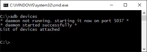
2.1 Keyin adb devices
2.2 Zjg6MDI6Nzg6ODE6MDA6MWI is device id for example
2.3 If there is not any devices, please check USB cable or driver in device manager

ADB help

1
2
3
4
5
6
7
8
9
10
11
12
13
14
15
16
17
18
19
20
21
22
23
24
25
26
27
28
29
30
31
32
33
34
35
36
37
38
39
40
41
42
43
44
45
46
47
48
49
50
51
52
53
54
55
56
57
58
59
60
61
62
63
64
65
66
67
68
69
70
71
72
73
74
75
76
77
78
79
80
81
82
83
84
85
86
87
88
89
90
91
92
93
94
95
96
97
98
99
100
101
102
103
104
105
106
107
108
109
110
111
112
113
114
115
116
117
118
119
120
121
122
123
124
125
126
127
128
129
130
131
132
133
134
135
136
137
138
139
140
141
142
143
144
145
146
147
C:\>adb
Android Debug Bridge version 1.0.32
-a - directs adb to listen on all interfaces for a connection
-d - directs command to the only connected USB device
returns an error if more than one USB device is present.
-e - directs command to the only running emulator.
returns an error if more than one emulator is running.
-s <specific device> - directs command to the device or emulator with the given
serial number or qualifier. Overrides ANDROID_SERIAL
environment variable.
-p <product name or path> - simple product name like 'sooner', or
a relative/absolute path to a product
out directory like 'out/target/product/sooner'.
If -p is not specified, the ANDROID_PRODUCT_OUT
environment variable is used, which must
be an absolute path.
-H - Name of adb server host (default: localhost)
-P - Port of adb server (default: 5037)
devices [-l] - list all connected devices
('-l' will also list device qualifiers)
connect <host>[:<port>] - connect to a device via TCP/IP
Port 5555 is used by default if no port number is specified.
disconnect [<host>[:<port>]] - disconnect from a TCP/IP device.
Port 5555 is used by default if no port number is specified.
Using this command with no additional arguments
will disconnect from all connected TCP/IP devices.
device commands:
adb push [-p] <local> <remote>
- copy file/dir to device
('-p' to display the transfer progress)
adb pull [-p] [-a] <remote> [<local>]
- copy file/dir from device
('-p' to display the transfer progress)
('-a' means copy timestamp and mode)
adb sync [ <directory> ] - copy host->device only if changed
(-l means list but don't copy)
(see 'adb help all')
adb shell - run remote shell interactively
adb shell <command> - run remote shell command
adb emu <command> - run emulator console command
adb logcat [ <filter-spec> ] - View device log
adb forward --list - list all forward socket connections.
the format is a list of lines with the following format:
<serial> " " <local> " " <remote> "\n"
adb forward <local> <remote> - forward socket connections
forward specs are one of:
tcp:<port>
localabstract:<unix domain socket name>
localreserved:<unix domain socket name>
localfilesystem:<unix domain socket name>
dev:<character device name>
jdwp:<process pid> (remote only)
adb forward --no-rebind <local> <remote>
- same as 'adb forward <local> <remote>' but fails
if <local> is already forwarded
adb forward --remove <local> - remove a specific forward socket connection
adb forward --remove-all - remove all forward socket connections
adb reverse --list - list all reverse socket connections from device
adb reverse <remote> <local> - reverse socket connections
reverse specs are one of:
tcp:<port>
localabstract:<unix domain socket name>
localreserved:<unix domain socket name>
localfilesystem:<unix domain socket name>
adb reverse --norebind <remote> <local>
- same as 'adb reverse <remote> <local>' but fails
if <remote> is already reversed.
adb reverse --remove <remote>
- remove a specific reversed socket connection
adb reverse --remove-all - remove all reversed socket connections from device
adb jdwp - list PIDs of processes hosting a JDWP transport
adb install [-lrtsd] <file>
adb install-multiple [-lrtsdp] <file...>
- push this package file to the device and install it
(-l: forward lock application)
(-r: replace existing application)
(-t: allow test packages)
(-s: install application on sdcard)
(-d: allow version code downgrade)
(-p: partial application install)
adb uninstall [-k] <package> - remove this app package from the device
('-k' means keep the data and cache directories)
adb bugreport - return all information from the device
that should be included in a bug report.
adb backup [-f <file>] [-apk|-noapk] [-obb|-noobb] [-shared|-noshared] [-all] [-system|-nosystem] [<packages...>]
- write an archive of the device's data to <file>.
If no -f option is supplied then the data is written
to "backup.ab" in the current directory.
(-apk|-noapk enable/disable backup of the .apks themselves
in the archive; the default is noapk.)
(-obb|-noobb enable/disable backup of any installed apk expansion
(aka .obb) files associated with each application; the default
is noobb.)
(-shared|-noshared enable/disable backup of the device's
shared storage / SD card contents; the default is noshared.)
(-all means to back up all installed applications)
(-system|-nosystem toggles whether -all automatically includes
system applications; the default is to include system apps)
(<packages...> is the list of applications to be backed up. If
the -all or -shared flags are passed, then the package
list is optional. Applications explicitly given on the
command line will be included even if -nosystem would
ordinarily cause them to be omitted.)
adb restore <file> - restore device contents from the <file> backup archive
adb help - show this help message
adb version - show version num
scripting:
adb wait-for-device - block until device is online
adb start-server - ensure that there is a server running
adb kill-server - kill the server if it is running
adb get-state - prints: offline | bootloader | device
adb get-serialno - prints: <serial-number>
adb get-devpath - prints: <device-path>
adb status-window - continuously print device status for a specified device
adb remount - remounts the /system and /vendor (if present) partitions on the device read-write
adb reboot [bootloader|recovery] - reboots the device, optionally into the bootloader or recovery program
adb reboot-bootloader - reboots the device into the bootloader
adb root - restarts the adbd daemon with root permissions
adb usb - restarts the adbd daemon listening on USB
adb tcpip <port> - restarts the adbd daemon listening on TCP on the specified port
networking:
adb ppp <tty> [parameters] - Run PPP over USB.
Note: you should not automatically start a PPP connection.
<tty> refers to the tty for PPP stream. Eg. dev:/dev/omap_csmi_tty1
[parameters] - Eg. defaultroute debug dump local notty usepeerdns
adb sync notes: adb sync [ <directory> ]
<localdir> can be interpreted in several ways:
- If <directory> is not specified, /system, /vendor (if present), and /data partitions will be updated.
- If it is "system", "vendor" or "data", only the corresponding partition
is updated.
environmental variables:
ADB_TRACE - Print debug information. A comma separated list of the following values
1 or all, adb, sockets, packets, rwx, usb, sync, sysdeps, transport, jdwp
ANDROID_SERIAL - The serial number to connect to. -s takes priority over this if given.
ANDROID_LOG_TAGS - When used with the logcat option, only these debug tags are printed.
C:\>

APK install to Embux Android deices from PC

4.1 Install directly

adb install XXXXX.apk

XXXXX is the apk file name.

4.2 Copy apk to device then install

adb root
adb remount
adb push XXXXX.apk /system/app

then

adb shell  

go to /system/app install it
or install it from device

WEC7 SD Flashing for ICM-Series

Posted on 2016-03-04

[Equipment]

  1. Laptop/PC with Windows OS (Windows 7 and Windows 10)
  2. EMBUX ICM board series
  3. Power adapter for ICM series
  4. SD card

[Environment]

  1. Windows Command Prompt
  2. Three major files released by EMBUX

[Procedure]

  1. Create a new folder in laptop/PC. ( e.g., new folder “embux-wec7” under D:\EMBUX )
  2. To flash bootloader and CE image into SD card, please copy the following 3 files to the new folder:
    ● cfimager.exe : The flash tool .exe file.
    ● EBOOT.nb0: The bootloader file
    ● NK.nb0: CE image file
  3. Plug SD card to laptop/PC with USB card reader.
  4. Make sure which drive that SD card has been mounted in Windows OS. (e.g., H:)
  5. Open command prompt in Windows OS.
  6. Navigate to the path of cfimager. (e.g., D:\EMBUX\embux-wec7)
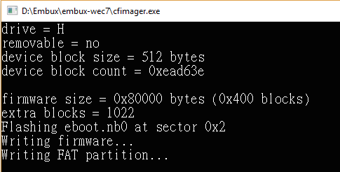
  7. Execute the flash command which can update bootloader image “EBOOT.nb0” to SD card:

● If this is the first time to flash a new SD card, the file system of SD card should be established. Please follow the steps as below:

1) Please enter the following command
cfimager -a -f EBOOT.nb0 -d SD card drive letter without colon -imx53

2) The flash tool, cfimager will start to execute:

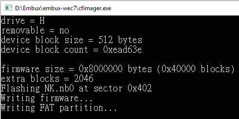
3) After flashing bootloader, please enter the following command to flash CE image

cfimager -a -f NK.nb0 -d <SD card drive letter without colon> -imx53

4) The flash tool, cfimager will start to execute:

5) Done

● If the SD card comes with existing EBOOT.nb0/NK.nb0 which need to be updated, please follow the steps as below:

1) Please enter the following command to update bootloader
cfimager -f EBOOT.nb0 -d <SD card drive letter without colon> -imx53

2) The flash tool, cfimager will start to execute

3) After flashing bootloader, please enter the following command to update CE image
cfimager -f NK.nb0 -d <SD card drive letter without colon> -imx53

4) The flash tool, cfimager will start to execute

5) Done

  1. Unplug the SD card and put it in EMBUX ICM board. Power on to start ICM series with WEC7.

Install Android Debug Bridge(ADB) in Windows

Posted on 2016-02-24

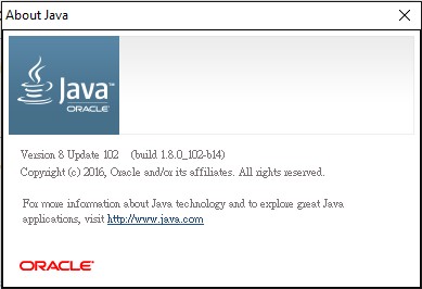
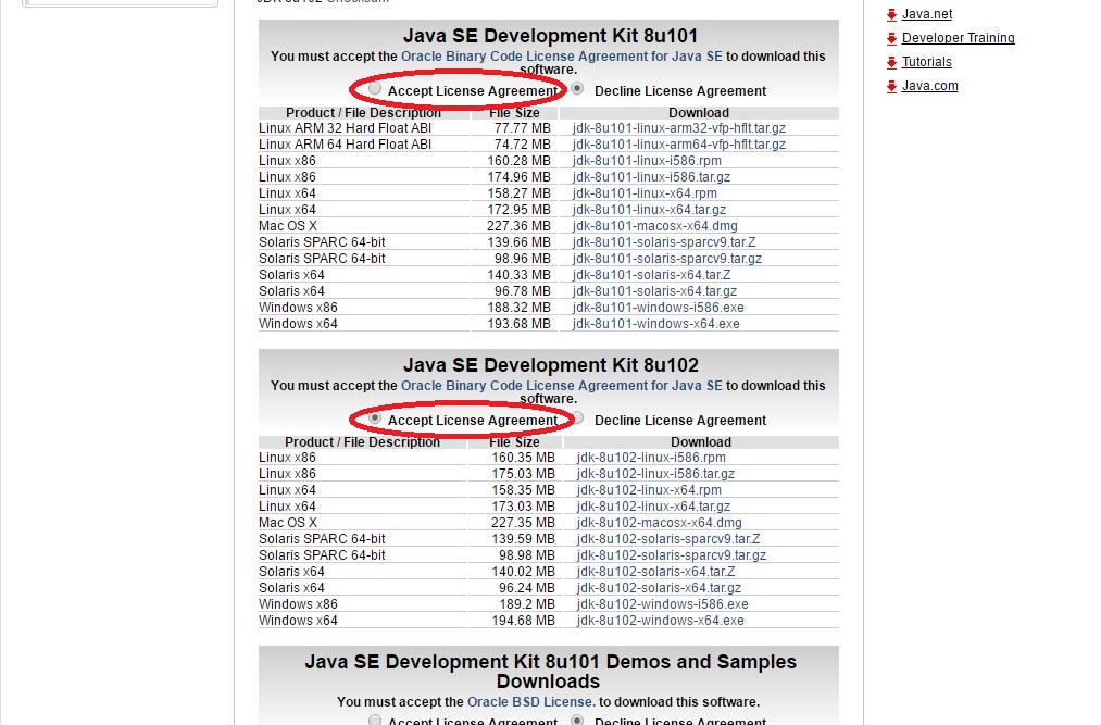
Check Java Development Kit

1.1 Click Start
1.2 Select All apps
1.3 Select Java
1.4 Click About Java
1.5 The Java version is listed

If Java is not available or version lower than 1.8, please download Java SE Development Kit, otherwise ignore follows.

1.6 Download the package per your system, check agreement as red before download.

1.7 Double click the .exe file what you downloaded.

1.8 Follow the setup wizard to install JDK.

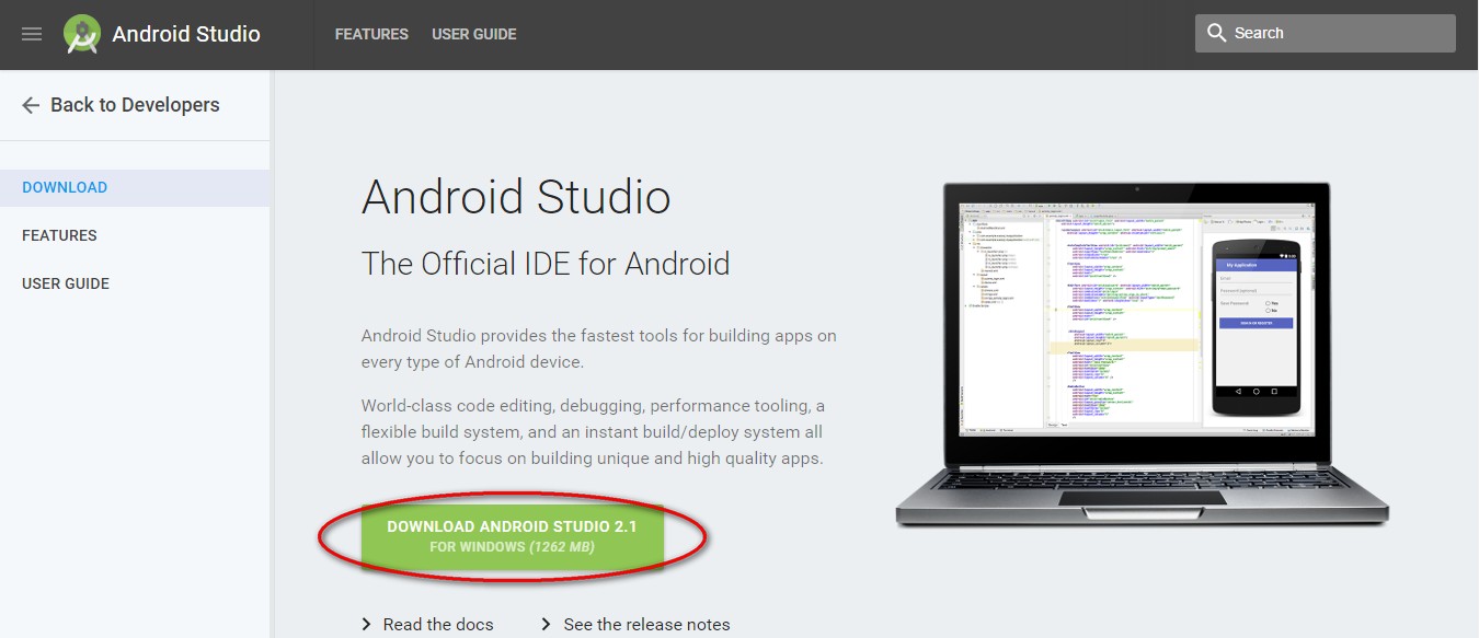
Download Android Studio

Android Studio
Click DOWNLOAD ANDROID STDIO 2.1 as photo.

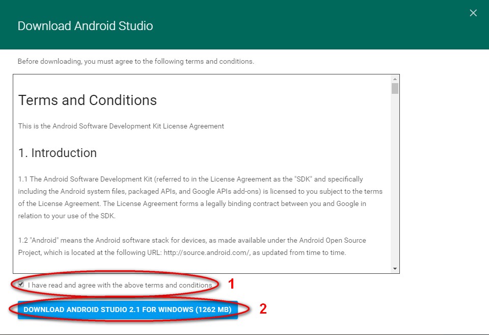
Agreement

3.1 Check I have read and agree with the above terms and conditions as step 1 in photo.

3.2 Click DOWNLOAD ANDROID STUDIO 2.1 FOR WINDOWS (1262 MB) as step 2 in photo.

Install

4.1 Launch the .exe file what you downloaded.

4.2 Follow the setup wizard to install Android Studio.

Yocto Qt sdk installation

Posted on 2016-02-16 | In yocto

Yocto Qt SDK Installation

Environment

Linux OS (Ubuntu 14.04)
QT 5.x (Qt creator 3.4.x or later)

Target OS version: yocto 1.6.2

Download:

  1. SDK file: poky-eglibc-x86_64-meta-toolchain-qt5-cortexa9hf-vfp-neon-toolchain-1.62.sh
  2. QT creator 3.4.2: qt-creator-opensource-linux-x86_64-3.4.2.run
    (You could find other version from Qt website)

Set-up step:

Install yocto sdk in your PC

1
2
3
$ sh ./poky-eglibc-x86_64-meta-toolchain-qt5-cortexa9hf-vfp-neon-toolchain-1.62.sh
destination path: “/opt/poky/1.6.2”
1
2
$ chmod _x qt-creaotr-opensource-linux-x86_64-3.4.2.run
$ ./qt-creaotr-opensource-linux-x86_64-3.4.2.run

Setup building environment for yocto in QT Creator

(e.g.) Assume the QT creator is locate in: ~/qtcreator-3.4.2/bin

$ ~/qtcreator-3.4.2/bin/qtcreator.sh
1
2
3
4
5
6
7
#### Setup yocto sdk environment
Select menu bar "Tools -> Option"
##### Build & Run -> Compilers -> Add Add → GCC (e.g.)Name: yocto-1.6.2 Path: Path :/opt/poky/1.6.2/sysroots/x86-64-pokysdk-linux/usr/bin/arm-pocky-linux-quneabi-g++ ##### Build & Run -> Debugger -> Add (e.g.) Name: debugger-yocto1.6.2 Source Path: Miruki/opt/poky/1.6.2/sysroots/x86-64-pockysdk-linux/usr/bin/arm-pocky-linux-gnuaebi/arm-pocky-linux-gnuaebi-gdb ##### Build & Run -> Qt version -> Add… Add → GCC
(e.g.)Name: Qt-yocto-2.0.5.5.1(qt5) Path: /opt/poky/1.6.2/sysroots/x86_64-pokysdk-linux/usr/bin/qt5/qmake ##### Build & Run -> Kits -> Add Add → GCC
(e.g.)Name: yocto-1.6.2-kit Device type: Generic Linux Device Sysroots: /opt/poky/1.6.2/sysroots/cortexta9hf-vfp-neon-poky- linux-gnueabi Compiler : GCC-yocto1.6.2 Debugger : debugger-yocto1.6.2 Qt version :Qt 5.2.1 (qt5) #### Init yocto environment Close Qt Creator which is opened in the last step
$ cd /opt/poky/1.6.2 /* change to yocto sdk directory */ $ source /opt/poky/1.6.2/environment-setup-cortexta9hf-vfp-neon-poky- linux-gnueabi /* run yocto sdk environment script by this command: */ $ ~/qtcreator-3.4.2/bin/qtcreator.sh /* run Qt creator again */

After these actions, you can build Qt application in our yocto system.

Reference

  1. Install Qt 5 on Ubuntu
  2. How to install Qt Creator
123…5
embux.io

embux.io

44 posts
8 categories
52 tags
© 2017 embux.io
Powered by Hexo
Theme - NexT.Mist